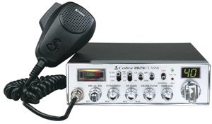
It’s one of the most popular modifications to have done to your CB radio. You’ll often hear people say on the radio that their Cobra 29 LTD has had a “swing mod” or “Super mod” done to it. On ebay people often will tell you that the radio they are selling has had a swing modification done to it to make it a “screamer”.
So what exactly IS the famous “super modulation” modification?
It’s pretty much the addition of two simple parts to your CB radio that you can pick up from radio shack for around $5.
Wow! A modification to my radio that costs $5 and will give my loud modulation? Yep.
Now this modification is not for everyone, and it does require a little soldering, But if you have an old Cobra 29 LTD or Cobra 25 LTD laying around it’s a fun modification to learn.
The first thing to know about this modification is that you don’t need a special “kit” to do it. Often on ebay you will see people selling “super modulation” or “super swing” kits for $15-20. Although the kits will work, they aren’t necessary. You can get all of the parts you need for this mod at Radio shack.
As mentioned there are different variations of this modification. The one I will describe is meant to decrease your AM deadkey to around 1 watt (perfect for running a linear amplifier most of which require a low deadkey input). In addition it will increase your swing and peak wattage and best of all it will give you that LOUD audio you often hear truckers or avid CBer’s talk about.
Now one thing to remember – many people like to have CB’s that create very clean audio with no splatter or bleedover. Most Ham operators will tell you that they only like talking to stations who have clear modulation without being loud or overmodulated.
Many CB technicians can do this type of modification but can also make the necessary adjustments to give you both a LOUD signal without being overmodulated but this requires specialized equipment that most CBer’s don’t have available.
Do not do this modification if you are someone who wants clean, clear modulation. Doing this modification to your radio may cause your radio to have bleedover into speakers, neighbors TV’s etc.
And now for the warning:
WARNING: Modifying your CB radio is illegal. I don’t promote it or condone it. I’m merely providing information. In addition I make no guarantee to the validity of any of this info. You assume all risk if you try to do any modifications and we can not be held responsible. I’m not a CB technician so this information is being provided by an amateur unskilled individual. Proceed at your own risk.
Okay – now that we’ve explained that let’s continue.
What you will need for this modification is two parts from radio shack –
1) 220uf (16-25 volt) electrolytic capacitor (the 470uf version will also work and people have also used a 1000uf version)
2) 33ohm, 68ohm or 100 ohm (1/4 to 1/2 watt) resistor (ohm resistance determines deadkey, more ohms=lower deadkey)
I also suggest that you have a watt meter so you can test your output before and after – and also so you can make adjustments if necessary.
Now – different value resistors offer different resistance, so I can’t tell you exactly which resistor will be perfect for your installation. Some resistors will give you a 1 watt deadkey, some will give you a 2 watt deadkey. A pack of a couple costs $0.99 so you might as well buy a couple different values and that way you can experiment if you first choice doesn’t work out.
Next thing you will need to do is to remove the screws for the top and bottom covers on your radio.
Now we will go step by step
1) Flip your radio upside down so the speaker is facing up.
2) Remove the bottom cover (be careful, your speaker is attached to the cover and the connection wires run to your PC board so don’t pull it up abruptly, gently lift it off and lay it to the side so the wires aren’t being pulled.)
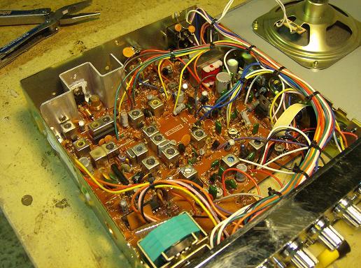
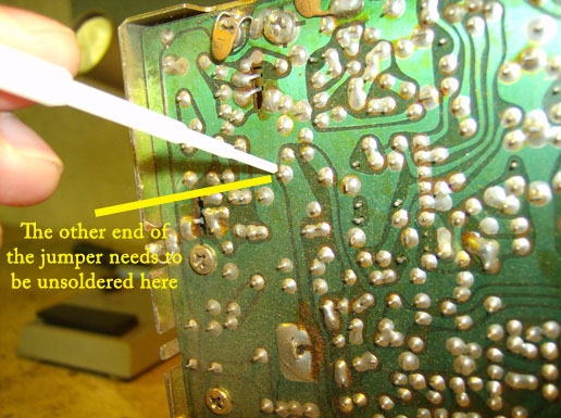
3) Now you should be looking at the component side of the PC board. You will see that the board has a lot of small labels on it in white lettering. Look toward the rear of the radio and locate JP36.
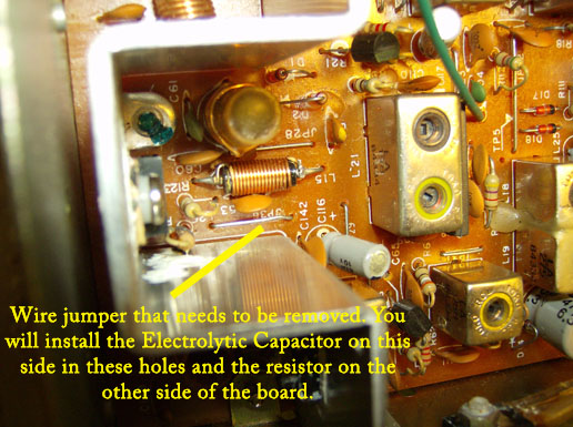
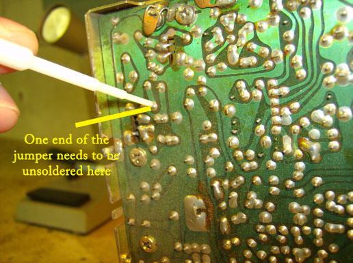
4) Once you have located JP36 you will need to remove it. To do this you will need to flip the radio over, remove the top cover, and unsolder each end of the jumper on the solder side of the PC board.
To locate the ends of the jumper on the solder side see the picture below.
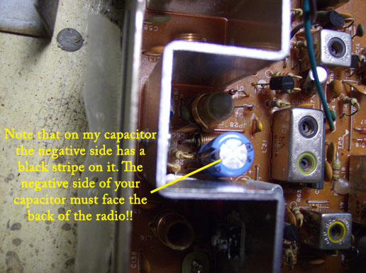
5) Once the jumper is removed you can fit the legs of your electrolytic capacitor into the empty holes. (VERY IMPORTANT NOTE: The electrolytic capacitor has a NEGATIVE and POSITIVE SIDE to it. When installing make sure the negative side is installed closest to the back of the radio.)
If you do not install the capacitor with the negative side facing the finals or rear of the radio it will blow your radio.
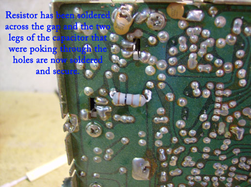
6) Now you will need to solder the cap into place on the solder side of the PC board. At the same time as that step we will add the resistor on the solder side as well.
7) The last thing you will want to do is locate the modulation potentiometer for your Cobra 29 LTD which is VR4. Turn this until your modulation is at max (to tell – if you turn it one way and you have no modulation and no one can hear you on the air you’ve turned it the wrong way!)
8) Some people recommend adjusting L14 for maximum power, but in most cases after doing the modification your swing should be better than before and your radio much louder so trying to squeeze a couple of extra watts is not my recommendation.
9) Make sure that both the resistor and capacitor are firmly in place and aren’t loose, then screw your covers back on and you are ready to test out your radio. (A watt meter is needed to see the results of course.
Many people do this modification because most amplifiers like deadkey input of 1-2 watts and most stock radios have output of 3-4 watts (not a good combo if you want your amp to last a long time).
Some people want to be able to turn the power down for running an amplifier and then turn it back up to run without one. There is a way to do this and add variable power to your Cobra 29.
Basically you would do the modification above – but when you solder in your resistor you would also need to solder a wire to each side that is long enough to reach the front knobs of your radio.
Find the back side of your RF gain knob – it will have two wires coming off of it. Clip those wires and then strip a small section off of each and solder them together.
Now you shouldn’t have any wires running to your RF gain knob.
Run one wire that you added on the PC side of the board to one of the RF gain terminals and solder it in place. Then run the other wire to the other terminal and solder it in place. Make sure to use the same terminals that the original RF gain wires used.
Once done your RF gain will now control your variable power. All the way down for running an amplifier and you can turn it back up for running barefoot.
Make sure you hook those two wires from the RF gain together that you clipped – if you don’t follow that step you’ll have no receive 🙂
The modification above can also be done on a Cobra 25 LTD – the only difference is that on the Cobra 25 LTD the jumper is labeled as JP6.