Motor Mauls – what are they and how do they work
CBradiomagazine.com thanks “Manic” for authoring and submitting this article!
SO– you are interested in how a motor maul works?
Basically, a motor maul is a mobile power supply– that allows the radio operator to run a larger amplifier, that would otherwise not be possible– without adding custom-mounted alternators, regulators, and large battery banks.
First, you must use a class C amplifier– that has a copper circuit board, with ‘better than average’ internal components. Amplifiers with printed circuit boards and solder traces, will not work well when volted. The purpose of “volting” is to push the amplifier to beyond its safe and capable levels for a short period of time. This will give the operator a power advantage when keying against another operator, with the same size amplifier.
The transistor data sheets for the 2sc2879 transistor do not measure output for anywhere near these voltage levels– so the data sheets (or voltage/current ratings) do not apply.
I strongly recommend competition-grade amplifiers. Stick with trusted names in the business. Just to name a few— Dave Made, X Force, and Fat Boy. — I personally recommend going with external driver amplifiers, and connecting only the last amplifier in line to the motor maul. Many radio operators have ran 1×4, 2×4, or even 2×8 amplifiers (with an internal driver section) with no problems on a motor maul….. But– I don’t recommend doing this…., and after you read this entire explanation, I think you will understandably agree– when you connect the motor maul to an amplifier with an internal driver, you are ALSO volting the driver section– meaning: you will be driving the final section harder than the builder intended– possibly over driving it.. You don’t need to drive an amplifier to its max when it is volted up.
Over Driving + Over Volting = plenty of smoke
detailed installation instructions/explanation — below….
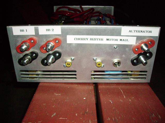
The 400 amp motor maul will replace multiple alternators by using FOUR 12 volt batteries. (A minimum of 800 cca each)– All of the batteries must be the same brand/model– along with the same age/and purchased at the same time. (This will ensure the batteries have more of a chance to equally hold a charge).. The motor maul’s charge lead is connected to the vehicle’s starting battery under the hood– and the stock alternator… This is the standard 12 volt charging system, and this is what keeps the FOUR added batteries charged, that are installed after the motor maul.. When the motor maul is activated (radio key up)– a relay inside the motor maul engages, which disconnects the 12 volt charging system from the motor maul. (you can run a motor maul in a computer-controlled vehicle).. Then, the motor maul has another relay– bu this time it closes, so the added FOUR batteries transfer from a parallel circuit to a series circuit – and the voltage is increased to 24 volts.
This series circuit is controlled with a variable regulator, on a wired remote control. The voltage can be selectively adjusted anywhere from 12 to 20 volts, from the driver’s seat. Keep in mind– the lower the voltage, the harder the motor maul will have to work… The higher the voltage, the harder the amplifier will have to work..
So, you must find a happy medium that agrees with both the motor maul AND the amplifier. I have found 17 to 18 volts works best. An external volt meter must be used. Some prefer digital volt meters, I personally prefer analog volt meters. The one I use was built for precision measurement. Very similar to a Bird watt meter, but it measures volts. (automotive-type voltmeters are not recommended, they are not as accurate as the other types)
Speaking of meters– I highly recommend monitoring your amplifiers wattage output, using a dual-line section, dual display meters, and watt slugs– parts from the Thruline watt meter, made by Bird Electronics. This wattmeter IS the industry standard, from which all other meters are measured. You can connect extension cables to the dual-line section, and mount the display meters up front– near the driver’s seat. The meters will just be a glance away. Monitoring forward and reflected watts could prevent a costly mistake, if anything goes wrong.
The motor maul is connected through the coaxial cable, between the radio and the first amplifier in line. How this works, is that the motor maul samples transmitted RF energy from the radio, when keyed up. This sample tells the motor maul to switch from “charge mode” to “key mode” … You want this “switching” to happen as quickly as possible– so you want the motor maul next in line after the radio, so that the motor maul is switched to “key mode” before the RF signal reaches the amplifier that is connected to the motor maul. There is a way to connect an external switch, so you can switch modes manually– but I personally have not tried this.
Charge Mode: the FOUR batteries after the motor maul, are charged from the alternator, through the battery under the hood– using a cable connected from the positive lead from the battery under the hood, to the positive charge lead on the motor maul.
Key Mode: the FOUR batteries after the motor maul, are being pulled from– by the last amplifier in line, on a 24 volt system (relay switched series circuit)– stepped down to a selectable voltage between 12-20 volts, using a variable voltage regulator, with a wired remote.
Installation notes: Use a minimum of 4ga cable– for charge lead, and cables to connect the 4 added batteries to the motor maul. I personally use 2/0ga welding cable (all power/ground), and a 250 amp alternator.. I also use TWO 8D lead-acid batteries.. (TWO 8D’s equal SIX group 31 semi-truck batteries).. Lead-Acid batteries recover faster than AGM (absorbent glass mat) or “sealed/maintenance-free” batteries. But, Lead-Acid batteries emit fumes– they are not recommended for install in closed quarters. Give plenty of room for ventilation, when using Lead-Acid batteries.
IMPORTANT: use exact length cables from each battery to the posts on the motor maul. If not, the current will be looking for the shortest and easiest path, and the signal (while in “key mode”) will be unbalanced. Also make sure the cables are well-insulated, and will not short out on the outer metal case of the motor maul.
DO NOT independently ground the batteries after the motor maul. Or the amplifier that is connected to the motor maul. Ground them to the correct labeled posts —or the adjoining cables— on the motor maul. (observe polarity). You must ground the negative charge post on the motor maul directly to the frame (this is the combined ground for the batteries and amplifier connected after the motor maul — so a sufficient ground is very important.
Antenna System –
Do Not run an antenna that has an SWR reading any higher than a 1.2 for best results .. A drill-through antenna mount is highly recommended (chassis ground). Use RG-213/U coax as a minimum, out of the back of the last amplifier in line (400 amp motor maul). Use an Antenna that is rated for at least twice the peak wattage output of your last amplifier in line. Open-Coil antennas are recommended. From my personal experiences- I have found that antennas with bolted-on coils, or two or more metal types on the same antenna– do not work well.