Working on your own CB – adjusting the modulation
** Warning performing modifications on a CB radio can be a violation of FCC regulations. Additionally it can be dangerous and may expose you to electrical shock, injury, or death. CB radios can easily be damaged when tampered with by an untrained individual. This website assumes no responsibility and can not be held liable for the activities or actions of anyone visiting this page.
For many people a CB radio is a mysterious box that allows them to rag chew everyday with their friends. They have no idea how the radio works other than they know how to turn it on, adjust the volume, push the key, and talk. And for many people thats as much as they will ever know about how a CB radio works. But for many of us who become involved in the hobby that isnt enough.
A CB radio is a complex piece of equipment and so Im not going to tell you that with a couple of simple tools youll all of sudden be a CB radio technician, but with a little patience you can do a number of small repairs and modifications yourself that are easy and effective. The one Ill mention today is how to adjust the internal modulation potentiometer inside your radio.
The first thing to know is that whenever you work on a CB radio you should have the proper tools and a static free environment. A static charge can build up very easily especially in places with dry air. Static electricity and CBs dont mix.
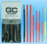
The two things you can do to avoid problems is to buy a set of Alignment tools (often called TV repair tools) which usually consist of 8-10 plastic pieces which vary from flathead to hex heads. Also you’ll want to buy a Static Grounding Clamp / Strap which helps reduce the risk of static going into your radio.
Example of a Alignment Tool Kit
ADJUSTING YOUR MODULATION
Once you decide to take your first jab at doing work on a CB one of the best things to be able to know how to do is internally adjust your radios modulation. 90 % of CB radios out there have a potentiometer (basically an adjustable resistor) that is mounted on the radios PC board and controls the level of modulation for the radio. Ideally youll want your radios modulation level to be 100%. Many radios come from the factory set for less than 100% and are not seeing their full potential, so raising the level will help your voice to be heard and will often increase the PEP wattage of your radio.
(For more information on what modulation is or how it effects your CB click here.)
First what you will want to do is disconnect the power to your radio. Next youll remove one or the covers of your radio so you can have direct access to the component side of the PC board. How can you tell which side is the component side? Well on your PC board one side has a bunch of solder spots and metal traces, this is the solder side, the other side has a number of capacitors and resistors visible, this is the component side.
Usually to access the component side of the board youll have to remove the cover of your CB that contains the speaker. The speakers are attached directly to the bottom cover with screws and then have two small wires that run to your PC board. When removing your bottom cover that contains a speaker be very careful not to pull it away from the radio too far or youll possibly cause the wires to your speaker to rip loose. The best way to remove the cover is to lightly pull it up till its free of the CB frame and then gently lay it on one side of the radio so that the speaker wires have slack and are not under stress.
Now you can see the guts and components of your radio. But how do you determine where the modulation potentiometer is when there are so many similar parts on the board?
Well the truth is, there is no easy way, but luckily there were people before you who figured it out and the information is readily available on the internet for you to look up.
A good website for radio modifications is http://www.radiomods.co.nz
Imagine we are looking for information on a Cobra 29 LTD Classic.
The particular page that has modification information for Cobra CBs is http://www.radiomods.co.nz/cobramodslist.html and on this list we can find that the modulation potentiometer for our Cobra 29 LTD Classic is labeled as VR4 on the PC board.
So now youll need to look careful at the component side of the PC board until you locate the potentiometer with VR4 labeled next to it.
Most modulation potentiometers inside CB radios look something like this
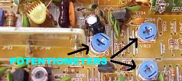
Once you locate VR4 youll want to use your alignment tool to turn it left or right to adjust the level of modulation.
Turning it one way will reduce modulation and turning it the other way will increase modulation. Radios and their components vary greatly so often the only way to discover which direction increases modulation is trial and error.
If you dont have a watt meter or modulation meter handy the easiest way to tell if youve increased or decreased modulation is to have a buddy available to listen on another CB radio.
If you turned down the modulation to 0% and try to talk to him, he wont hear you. If youve turned the modulation potentiometer in the correct direction he should hear you easily and you should sound louder than you did before your adjustments.
Make sure you dont turn up your modulation too much as this will result in over-modulation.
Once youre done with your adjustments you can put your covers back on, power up the radio and start talking!
Remember that having work done on your radio is always best done by a professional, but if you feel like trying your hand at certain things the only way to learn is to try. Ive made many adjustments in many radios myself and although often my methods may not have been conventional I was able to achieve the desired result.