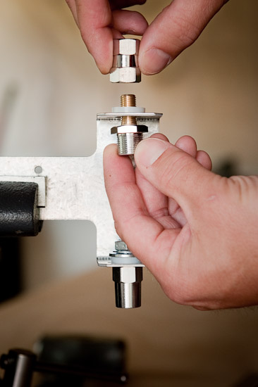
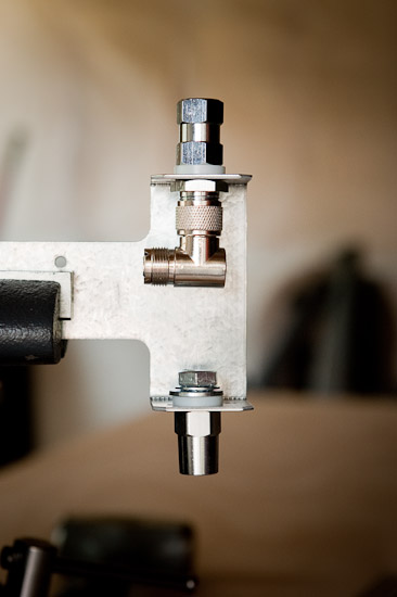
Written By: Scott Wolfington
The following article is based on a HamUniverse.com article by John Reisenauer (KL7JR) titled Simple and Inexpensive Dipole and V Antenna Mount.
First, I must say that setting up a base radio (11 meter) and accompanying antenna is a new hobby for me. I’m a complete newbie. When I first started working on my 11M CB base station, I knew I had to figure out a way to get an antenna up without breaking any of my neighborhood rules. I live in a subdivision governed by a Homeowners Association, so we have certain rules that prevent homeowners from erecting/mounting antennas on their houses. An 18ft Solarcon A99 was out of the question.
After doing some research, I learned that a dipole antenna mounted in my attic might do the trick. About this same time, I came across John’s article on HamUniverse.com describing a dipole antenna he made using mobile fiberglass type CB antennas. Making a dipole antenna from off-the-shelf items that could easily be purchased from the local truck-stop (Travel America) and hardware store (Lowes) sounded great to me. Plus, with it mounted in my attic, it would be the perfect “stealth” antenna to keep the homeowners assocation happy. Could it work for 11M CB? I didn’t know. Afterall, his article was on a “HAM RADIO” website.
After reading John’s article, I had some questions so I emailed Don (N4UJW) at HamUniverse.com. Don responded to me promptly and put me in touch with John directly. John was glad to answer any questions I had.
Before we get into the actual antenna assembly, let’s look at a few pictures illustrating my installation. The antenna is in my attic, and my 11 meter CB base radio is in my kitchen. To connect the two, I purchased 100ft of “Davis RF 9914F Bury-Flex 50 ohm Heavy Duty Coax“. I found it on eBay for about $90 (US Funds). It’s GREAT stuff!
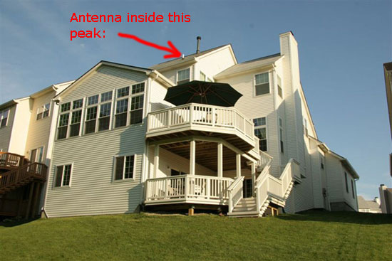
Picture showing which attic in the house I mounted the antenna. The back of the house
faces South. As you can see, there are lots of other houses around.
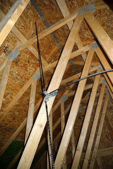
Antenna Mounted Vertically In Attic
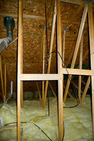
Antenna Mounted Vertically In Attic
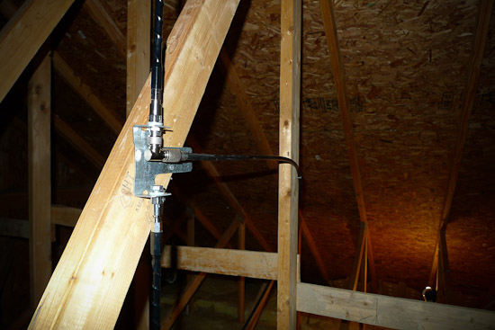
Antenna Mounted Vertically In Attic
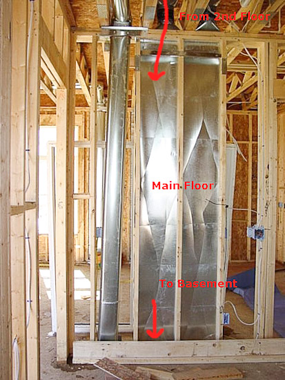 |
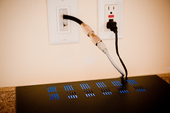
Ran the coax across the basement ceiling, and up into the kitchen. I like that brush wall-plate.
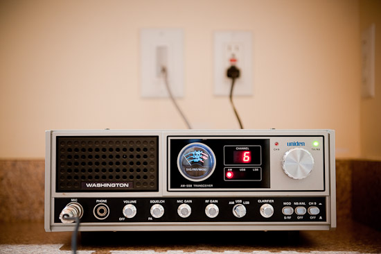
The coax terminates at my Uniden Washington base station. Nice radio.
Antenna Tuning – High SWR
After getting everything installed, I realized the antenna was giving me high SWR readings. The SWR was in the high 2’s on Channel 01 and 20, and 3+ on Channel 40. It was time to start tuning the antenna. In my case, the SWR on channel 40 was greater than on channel 1, so the antenna was considered “LONG” and a reduction of conductor length is what was needed to correct it. There’s a tiny wire that wraps around the Firestik® fiberglass antenna forming a coil and goes all the way up to the tip. You can actually see it through the plastic sleeve of the antenna when looking at it closely. This wire is what needed to be shortened, not the fiberglass itself. Here’s a link to FireStik’s website with information about tuning an antenna: http://www.firestik.com/Tech_Docs/Setting_SWR.htm
NOTE: The following was done to both the top and bottom antenna. You want each antenna to be the same length. So, for example, when you read that I snipped 2 coils that means I snipped 2 coils from each antenna. Whatever I did to one antenna, I did to the other before checking SWR.)
Basically, you unwrap the coil and then snip. The first time I was a bit nervous, so I unwrapped and snipped off only two coils of wire. This didn’t change the SWR much. The next time I unwrapped/snipped off 4 coils. I saw a change in the SWR and it was getting closer to where it needed to be, but it was still not good enough. The next time I snipped off 5 coils (I probably shouldn’t have gotten this bold, but it ended up ok). After removing 11 coils of antenna wire so far, here were my SWR readings:
Channel 01: 1:1
Channel 20: 1.4:1
Channel 40: 1.6:1
It’s not too bad, but I wanted to snip some more. I decided to be SUPER conservative though. I didn’t want to cut too much wire and then end up back in the 3’s for my SWR because of a “SHORT” antenna. I made two more snips. The 1st snip I took off about 1/4 of a coil of wire. I saw a small change in the SWR reading. With the 2nd snip I took off another 1/4 of a coil of wire. My final SWR ended up being:
Channel 01: 1.05:1
Channel 20: 1.15:1
Channel 40: 1.45:1
I’m happy with those readings. During the tuning process, you may have noticed that channel 01 got down to a 1:1 SWR. On my last snip, it creeped back up to 1.05:1. I figured it was time to stop tuning, especially since the other two channels were both within spec now. It’s nice to know that this antenna was very tunable and a tuner is not required to use it. I think the hardest part of this project was tuning the antenna without a helper. It took some extra time to climb into the attic, snip some of the antenna, climb out of the attic, check SWR reading, climb back into the attic… I probably did that 5-6 times. I think my patience paid off though.
Long Distance Exchange (DX) And Local Talk Results
I’m in Ann Arbor, MI, USA. Over the last couple of days, I’ve heard 11 meter DX from Illinois, the Carolinas, Georgia, Texas, New York, New Jersey, Minnesota, Michigan, Ontario Canada, Ohio, Tennessee, Alabama, West Virginia, and Florida. Unbelievable to me, and very exciting! All from a home grown antenna built from mobile antennas and mounted inside my attic. How cool is that? When the DX isn’t active, I’m able to talk locally up to 3-4 miles. Here is a video showing some of the DX I’ve heard:
Antenna Assembly
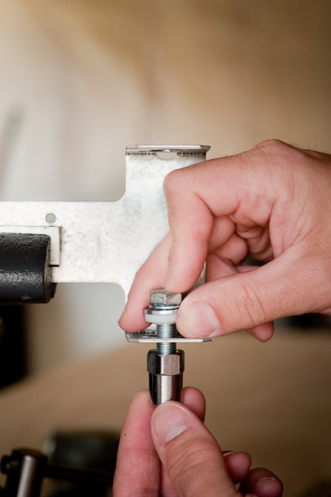
The antenna assembly was really straight forward. The only difference between my assembly and John’s (KL7JR) were the holes I drilled for the antenna mounts. The antenna mounts I purchased must have been a little larger than what John used because there wasn’t enough space for them to mount properly in the existing holes after bending the Strong-Tie “T”. If you choose to use the existing 3/8″ holes then you’ll need to drill them out since they aren’t quite large enough for the lip of the plastic spacer to fit properly. They need to be bored out to a 1/2″ diameter. Lets get started…
Parts List:
| QTY | ITEM |
|---|---|
| Simpson Strong-Tie “T” (Part #: 66T) – Purchased At Lowes | |
| Firestik® KW4 4ft Antenna – Click Here | |
| PL-259 L-Connector (Diesel Part#: 360-56201) | |
| Plug To Lug Connection – Stud Mount (Diesel Part#: 360-53401) | |
| Plug To Plug Connection (Diesel Part#: 360-53402 or 360-53403) |
| HINT: If you get the Strong-Tie “T” from the Lowes website, search for Simpson 66T. The other items on the list can be found at many CB shops, truck stops, or antenna accessory suppliers. |
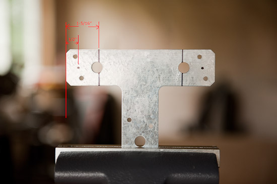 |
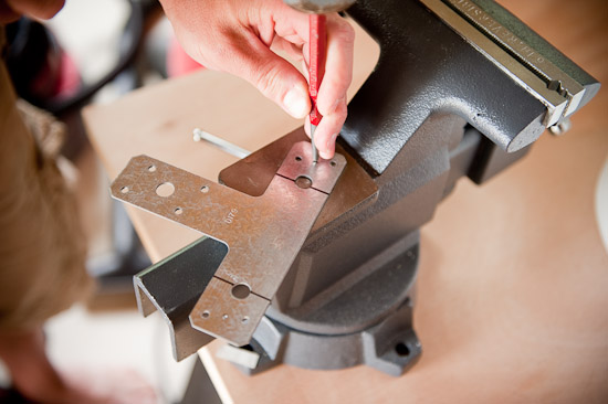
| Step 1: Mark the locations for the new antenna mount holes, and the lines where you’ll bend the Strong-Tie “T”. See the image for measurements. |
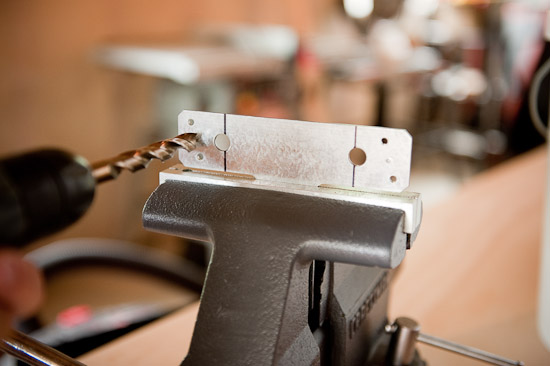 |
| Step 3: Drill the holes where the antenna mounts will attach to the Strong-Tie “T”. Make sure you use a 1/2″ drill bit. |
 |
| Step 4: You’ll probably end up with some sharp metal burs after drilling your antenna mount holes. Just take a metal file and file them down. |
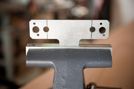 |
| Step 5: This is what your Strong-Tie “T” will look like once you’re done drilling the holes. Lookin’ good! Next you’ll be making the appropriate bends. |
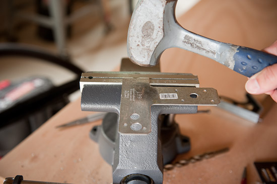 |
| Step 7: Keep hammering until you have a 90° bend. |
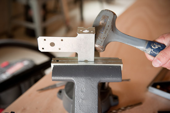 |
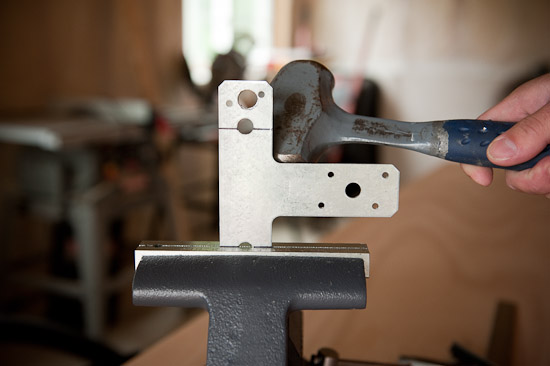
| Step 8: Flip the Strong-Tie “T” around and line up the other line just like you did in Step 6. Hammer away! |
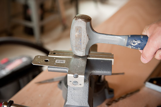 |
| Step 9: Keep hammering until you have a 90° bend. |
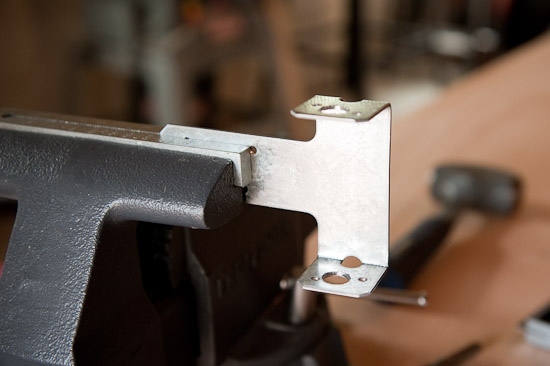 |
| Step 10: The completed Strong-Tie “T” antenna bracket. Lookin’ good! |
Questions? Comments?
Email: scott AT wolfington DOT net
© 2010 – Scott Wolfington
http://www.wolfington.net/articles/dipole/default.html

