MFJ-1890 10 Meter Moxon Antenna
(Tested on 10 meters & 11 meters/CB Band)

Recently I got my hands on MFJ’s new 10 meter Moxon antenna. The MFJ-1890 is a lightweight aluminum antenna designed to operate in the 10 meter band and we had hoped that with a little messing around we could get it to tune to the 11 meter cb band.
What is a Moxon antenna? Here is a quote from wikipedia for the definition:
“The Moxon Antenna is a simple two element parasitic array antenna that is popular with Amateur Radio enthusiasts for its simplicity of construction. The design is rectangular, with roughly half the rectangle being the driven element and the other half being the reflector. It can by thought of as a Yagi Antenna with bent elements and without directors.”
The antenna is credited to Les Moxon G6XN, and while it is well known by most ham operators, many CB’ers may be unaware of this design. The Moxon offers excellent front to back gain and good rejection as well. It’s footprint is probably the biggest positive attribute, as it’s only 12 feet in total length (6 feet on either side of the boom) and in a horizontal profile it’s a very stealthy-looking antenna compared to a Yagi or a V Quad.
ASSEMBLY AND ANTENNA WALKTHROUGH
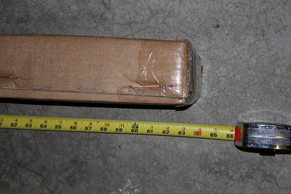
I think this antenna arrived in one of the smallest boxes I’ve ever received for a base style antenna. The box measured around 64″ in length and only about 5″ in width/height. I knew that meant some assembly would be involved, but just from the size and weight of the box I knew this would be a compact and lightweight antenna.
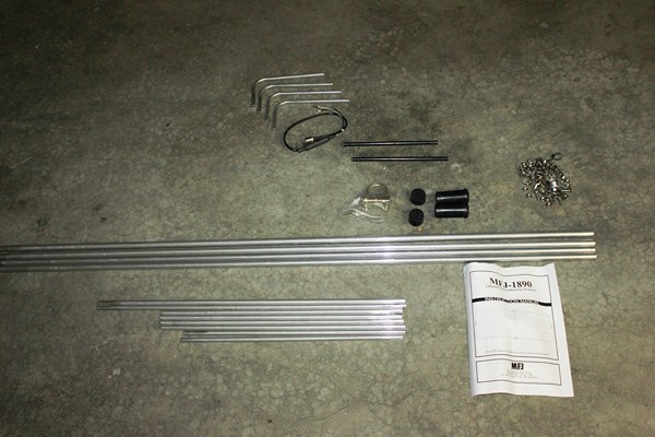
I got all of the parts and pieces spread out on the ground and you can see from the picture above that there really isn’t a whole lot going on. You have a couple of longer pieces of aluminum, three lengths of shorter pieces, a couple of end caps, some nylon separator pieces, some aluminum elbow pieces, your wiring connector and a bunch of clamps and hardware. We’ve scanned the assembly instructions and you can view them by clicking HERE (MFJ-1890 Instructions PDF)
Below I’ve included images of the aluminum and hardware.
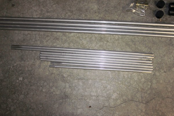
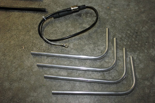
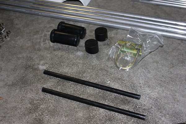
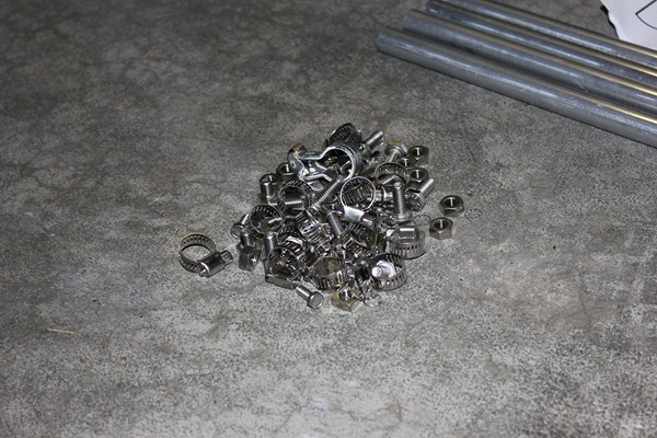
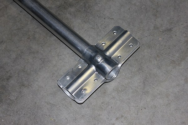
Assembly was relatively easy and took about an hour. The end clamps above were probably the toughest part of putting the antenna together and it was mostly my own ineptitude that made me spend an extra ten minutes figuring out how the small set screw inside was supposed to work.
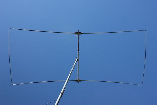
The antenna comes with everything you’ll need – the boom, mast mount, and coax connector. All you need is a mast or length of pipe to attach it to and you’re ready to start talking.
Note: The Moxon style antenna is supposed to look like a rectangle and in the picture above and in subsequent pictures you’ll notice mine had a slight bend to it. It didn’t start out that way 🙂 It was a nice-looking rectangle when I assembled it for 10 meters according to the directions, but as I tuned the antenna for 11 meters and lengthened it I was hasty and didn’t take the time to also lengthen the points where it mounted on the boom. So while it is totally functional it doesn’t have the exact rectangle look it’s supposed to have in the pictures.
Flat plate clamps are used to attach the boom to the driven element and reflector. The reflector tubing will attach directly to the plate (pic 1 below) while the driven element tubing is embedded into insulators (pic 2).
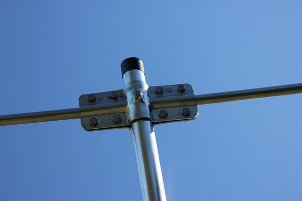
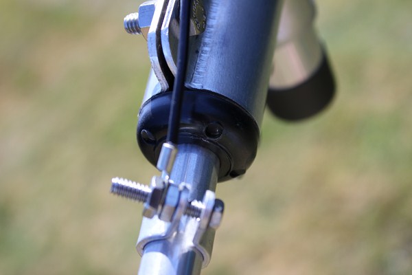
The two elements are separated by nylon pieces which slide into the aluminum tubing and are clamped in place.
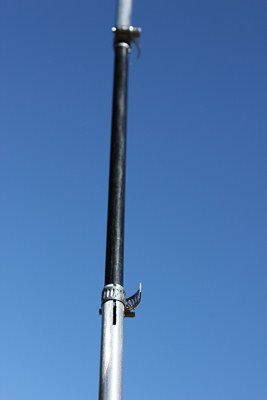
The coax connector has two wires which attach to the driven element with small clamps/screws. The coax connector itself can be taped or zip tied to the boom so that the coax running down the mast doesn’t pull on the wires.
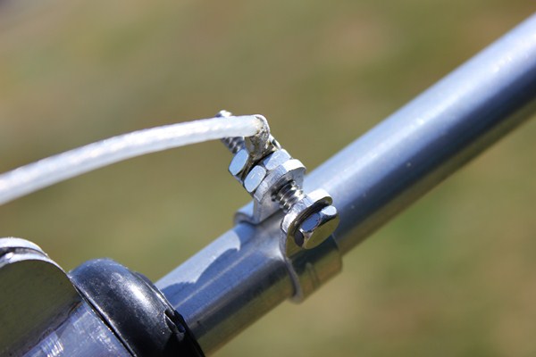
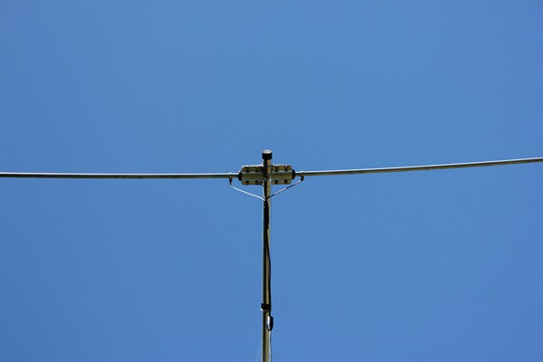
The antenna kit includes a U bolt-style clamp to connect it to your mast or pipe. We had some extra 1″ pipe laying around so we screwed two sections together and put the Moxon up roughly 20 feet in the air for testing.
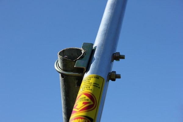
RESULTS
The assembly of this antenna is pretty simple, none of the parts or process was difficult and the end result is one of the lightest antennas I’ve ever lifted off the ground. Within two hours I had assembled the antenna and tuned it for 10 meters. At 20 feet off of the ground the SWR reading was 1.1 in the middle of the 10 meter phone frequencies.
I made multiple DX contacts immedately and after flipping back and forth on the antenna switch I found the antenna putting a stronger signal into stations than my Imax 2000. It only took a short time for me to feel the antenna was a strong performer on 10 meters but I wanted to know how well it would tune for 11 meters.
Lengthening the antenna was a fairly straightforward process and involved just extending all of the tubing pieces. After 20 minutes or so I found that to achieve a 1.2 SWR in the middle of the 11 meter band meant pulling all of the tubing section out to their absolute maximum (see picture below). This meant that they had to be extended to the very ends of the slit tubing pieces, leaving small openings in the tubing visible. If you were planning to run the antenna long-term like this I’d probably cover the exposed area just to make sure you don’t get water or foreign material inside the antenna.
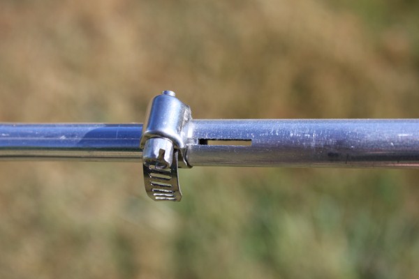
The antenna tuned fairly well for 11 meters but 1.2 was as low as I could get the SWR. The design is broadbanded enough that you could still go up to 10 meters and talk with around a 2.0 SWR. Not perfectly ideal but acceptable enough if you wanted to run both bands with one antenna.
As the DX faded I got a chance to test out the gain of the antenna versus my vertical antenna. Talking to a station 35 miles south of me, we first tested using our vertical antennas and then we switched to horizontal (he was using a 5 element yagi). As was expected the signals jumped way up with the beam antennas going from an S2 to around a S5-S7. Previously I had done some testing with this same station with the Maco V Quad and the station had a reported a strong signal horizontally but his station also received the V Quad signal on his vertical antenna. This wasn’t the case with the Moxon. He couldn’t hear me on the vertical at all; the signal polarization on the Moxon was definitely more horizontal than the V Quad.
We also tested the rejection and I turned the antenna around to see how much the signal dropped off and his signal went from a S5-S7 down to a S2. Quite impressive for a two element antenna.
The advertised forward gain for this antenna is 3.3 dBi and the front to back rejection is listed as 30dB.
Perhaps the best thing about the antenna is the price. At $84.95 it’s quite a steal, as I could easily spend that much in materials and time to build something much more primitive-looking. While the antenna is truly a 10 meter antenna it did perform quite well on 11 meters and I see this as an excellent antenna for installs where a larger 3 element yagi just isn’t possible. The antenna is so light it could easily be turned by a light duty TV antenna rotor and mounting this antenna using eave mounts or chimney mounts would be no problem.
My only reservations to using this antenna as a permanent 11 meter antenna might be that I had to max out all of the lengths of tubing and I don’t know how much this would reduce its structural integrity. I would love to see MFJ lengthen some of the tubing pieces so that it gave the antenna more flexibity to be tuned for either band. I think a lot of CBer’s who want the benefits of a beam without the large footprint will really be all over this type of design.
This probably hasn’t been the most scientific of my reviews (my antenna analyzer was on loan to a friend during my testing) but pure and simple this antenna works. I think it beats the V Quad design in terms of horizontal performance and in terms of total size. Whether you purchase this nicely-put-together kit or you make your own, the Moxon is definitely an antenna design I’d suggest everyone try.
